
Why build a self-balancing robot?
The aim of a self-balancing robot is to balance itself on two wheels, being able to drive around without toppling over. Self-balancing robots use a “closed-loop feedback control” system; this means that real-time data from motion sensors is used to control the motors and quickly compensate for any tilting motion in order to keep the robot upright. Similar self-balancing feedback control systems can be seen in many other applications. Some of the obvious examples include Segways, bipedal robots and space rockets (A few rockets have been lost due to a faulty balancing system).
But what many people don’t realise is that often the same type of controller is also used in a large variety of other applications which aren’t related to balance. Proportional-integral-derivative (PID) controllers are used by elevators to control their motion and position, used by air-conditioning units to control the temperature within a room, and even used to control the operation of jet engines. Of course rockets use significantly more complex controllers than air-conditioners, but the underlying principle is still the same: how to adjust the system in order to get as close to the desired target value (be it temperature, angle, or position) as possible. That is why building a self-balancing robot is so educational; you can use the same control methods over and over again for other projects. And don’t forget, self-balancing robots are a fun toy to play with! Here is a video of my self-balancing in action:
A Brief Overview
It takes several steps to build a self-balancing robot. The easiest part is the hardware, so that is always a good place to start. The robot requires two motors, a motor controller, a sensor to detect its current tilt angle, a micro-controller and some type of frame. Surprisingly enough due to the inertia of an inverted pendulum, the robot actually finds it easier to stabilise if the frame is very tall with a lot of weight on top, instead of a small frame with a low centre of gravity!
Once all of the physical components have been assembled, we can proceed to the tricky stuff; the software. As the system is inherently unstable and wants to topple over, the micro-controller needs to continuously monitor the current angle of the robot and be as fast and efficient as possible in order to retain its balance. While the loop time (refresh rate) should be short, it also needs to remain regular so that the control system can properly performs its calculations. For my robot I used a standard loop time of 10ms (100Hz). Therefore, the controller recalculates its response 100 times per second!
Required Components
Before we dive into how to make a self-balancing robot, we need to get our hardware together. Here is a list of the required component, with some links as reference:
- Essential:
- 1 x Arduino-compatible Controller
- 1 x Power Supply/Battery
- 1 x Motor Controller
- 1 x Gyroscope/Accelerometer Module (Eg. MPU-6050)
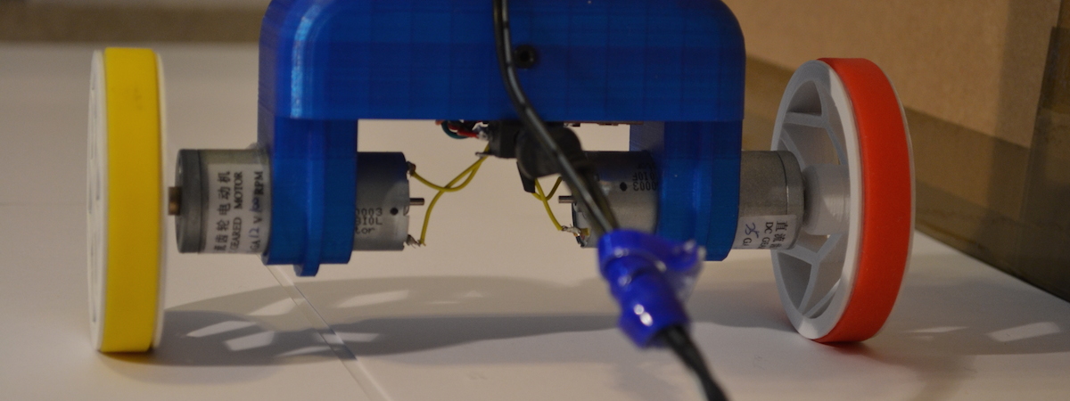
- 2 x High Torque Gearbox Motors
- Colour-coded wires, preferably single core
- Some type of frame!
- Optional:
- Some buttons to control the robot
- A on/off power switch
- A number of colourful LEDs
The links above are for reference only! I recommend that you look around for the best deals before buying anything.
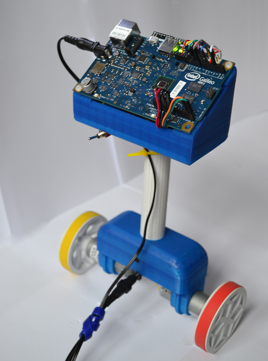
I decided to use the Intel Galileo Gen2 Development Board (now discontinued) for my micro-controller as I still had a couple lying around, and it is compatible with the Arduino environment. In reality you could use any board (Eg. Uno, Mega, Red-board) to make your self-balancing robot. In all of my robots I used the MPU-6050 sensor, which contains both a gyroscope and an accelerometer. The benefit of using both of the sensors together is that their data can be fused, giving us much stabler and more accurate readings for angle.
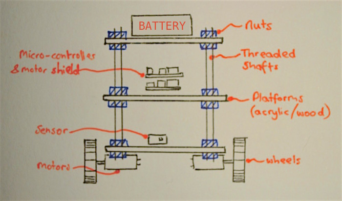
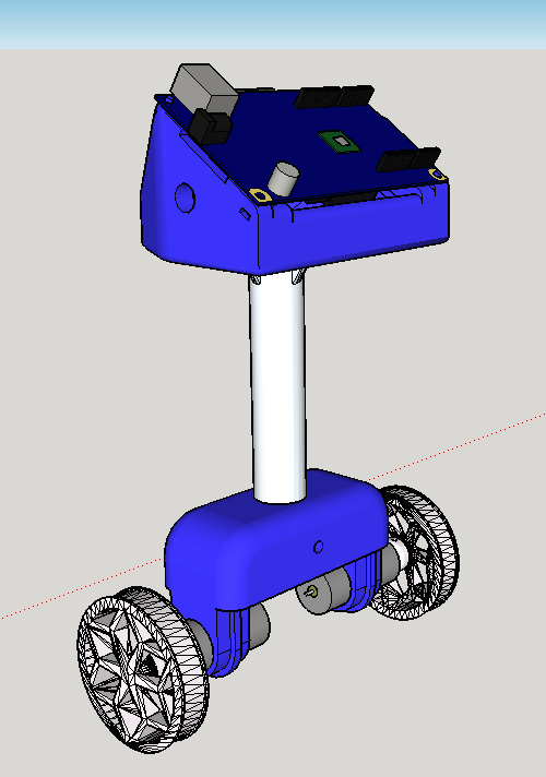
To create my frame I designed all of the components on the computer using SketchUp, and then sent them to be 3D printed. If you don’t have access a printer, an alternative would be to build your own frame out of scrap parts! I built my first self-balancing robot prototype out of lollipop sticks and glue, and I was surprised how well it worked! A frame design which I have commonly seen other people implement is to use a couple of plastic/wood rectangles as platforms, and to connect these using a long threaded bolt and some nuts (as shown in the diagram below).
Please leave a comment below if you have any questions or suggestions. In the next part of this tutorial I will cover the basics of how accelerometer and gyroscope sensors work, and how we can use them in our robot.
Updated: 23rd May 2019 – Reformatted post
Updated: 29th May 2020 – Updated the descriptions and reformatted post