If you haven’t already read the first part of this Self-balancing robot series, I would encourage you to do so now! The first section below deals with a little bit of theory behind the sensors, so if you want to get straight to the programming/building part, please feel free to skip to the second section…
Deciding which Gyroscope Module to Use
So you have decided to go ahead with the project and construct your own self-balancing robot? That’s great! Now we can start by looking at one of the most significant elements of this project; the sensor. Traditionally the sensor of preference for stabilisation is a gyroscope. Now-days gyroscopes are extremely small and very cheap to buy, so they are ideal for amateur electronics projects. Unfortunately these gyroscopes (both the cheap and the not-so-cheap versions) also come with their own problems. They are good for short-term and quick movements, but tend to drift over time as the error accumulates. They also record a lot of jitter and noise, which needs to be filtered by the micro-controller before the data can be used.
To reduce this drifting effect of the gyroscope, it is possible to combine the sensor data with that from an accelerometer. The accelerometer is good at sensing slower and more prolonged movements, rather than the fast motion. Therefore if we take the best of both worlds and fuse the data together, we will be left with an extremely accurate picture of the motion of the robot.
As a result I decided to use a combined accelerometer & gyroscope breakout module (the MPU-6050), which is slightly more expensive than a simple gyro, but should lead to a superior stabilisation performance. Note: the MPU-6050 comes with a library which does all of the sensor fusion calculations for you, so that definitely is a plus!
Getting started with the Accel-Gyro Module
The MPU-6050 uses I2C to communicate with the micro-controller, so I started by connecting up the pins as shown in the schematics: the SDA line connects to the Analog pin 4, the SCL to Analog pin 5, power input to the 3.3v pin and the ground to the GND pin. If you are using one of the newer Arduinos, you could also connect the sensor to the dedicated SDA and SCL header pins.
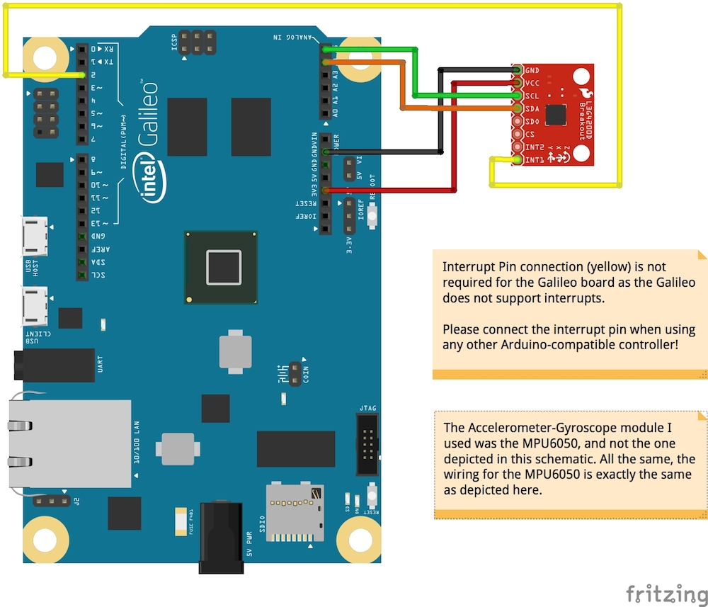
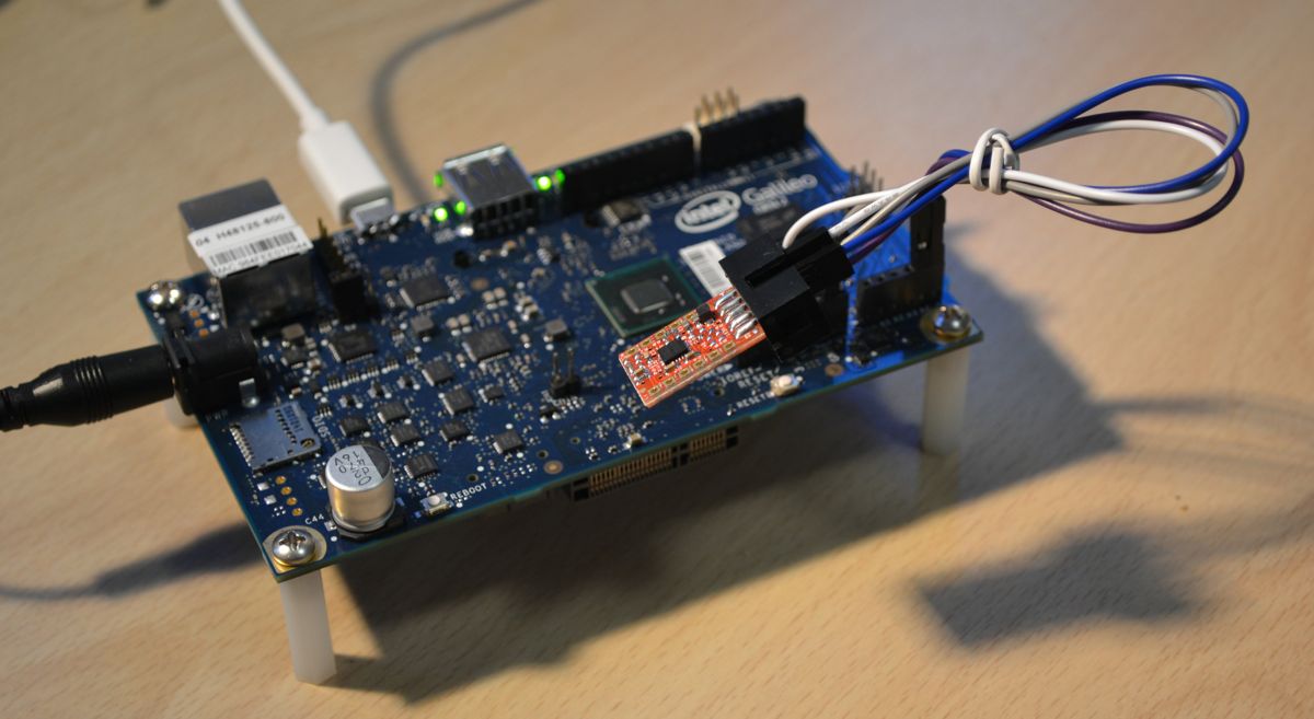
As I am using an Intel Galileo Gen2 board, I did not use the interrupt pin. In general it is very bad practice to disregard the interrupts, as it might cause the buffer holding the sensor data to overflow, but for some reason the Galileo does not support normal interrupts! In order to get the sensor working correctly on the Galileo Board, I spent a lot of time on getting the timing right so that there is no overflow of incoming sensor data.For all other Arduino-compatible board, you should use the interrupt so that the micro-controller deals with new sensor data the moment that it is sent. (The interrupt pin is connected to Arduino digital pin 2)
Now it is time to get some data from the accel-gyro module! To do this I simply used the sample code which came with the documentation of the MPU6050 in order to read the raw sensor data. For this sample to work, the I2Cdev and the MPU6050 libraries need to be installed. Here is the code:
// I2C device class (I2Cdev) demonstration Arduino sketch for MPU6050 class
// 10/7/2011 by Jeff Rowberg <jeff@rowberg.net>
/* ============================================
I2Cdev device library code is placed under the MIT license
Copyright (c) 2011 Jeff Rowberg

Permission is hereby granted, free of charge, to any person obtaining a copy
of this software and associated documentation files (the "Software"), to deal
in the Software without restriction, including without limitation the rights
to use, copy, modify, merge, publish, distribute, sublicense, and/or sell
copies of the Software, and to permit persons to whom the Software is
furnished to do so, subject to the following conditions:

The above copyright notice and this permission notice shall be included in
all copies or substantial portions of the Software.

THE SOFTWARE IS PROVIDED "AS IS", WITHOUT WARRANTY OF ANY KIND, EXPRESS OR
IMPLIED, INCLUDING BUT NOT LIMITED TO THE WARRANTIES OF MERCHANTABILITY,
FITNESS FOR A PARTICULAR PURPOSE AND NONINFRINGEMENT. IN NO EVENT SHALL THE
AUTHORS OR COPYRIGHT HOLDERS BE LIABLE FOR ANY CLAIM, DAMAGES OR OTHER
LIABILITY, WHETHER IN AN ACTION OF CONTRACT, TORT OR OTHERWISE, ARISING FROM,
OUT OF OR IN CONNECTION WITH THE SOFTWARE OR THE USE OR OTHER DEALINGS IN
THE SOFTWARE.
===============================================
*/

// I2Cdev and MPU6050 must be installed as libraries, or else the .cpp/.h files
// for both classes must be in the include path of your project
#include "I2Cdev.h"
#include "MPU6050.h"

// Arduino Wire library is required if I2Cdev I2CDEV_ARDUINO_WIRE implementation
// is used in I2Cdev.h
#if I2CDEV_IMPLEMENTATION == I2CDEV_ARDUINO_WIRE
	#include "Wire.h"
#endif

// class default I2C address is 0x68
// specific I2C addresses may be passed as a parameter here
// AD0 low = 0x68 (default for InvenSense evaluation board)
// AD0 high = 0x69
MPU6050 accelgyro;
//MPU6050 accelgyro(0x69); // <-- use for AD0 high

int16_t ax, ay, az;
int16_t gx, gy, gz;

#define LED_PIN 13
bool blinkState = false;

void setup() {
	// join I2C bus (I2Cdev library doesn't do this automatically)
#if I2CDEV_IMPLEMENTATION == I2CDEV_ARDUINO_WIRE
	Wire.begin();
#elif I2CDEV_IMPLEMENTATION == I2CDEV_BUILTIN_FASTWIRE
	Fastwire::setup(400, true);
#endif

	// initialize serial communication
	// it's really up to you depending on your project)
	Serial.begin(115200);

	// initialize device
	Serial.println("Initializing I2C devices...");
	accelgyro.initialize();

	// verify connection
	Serial.println("Testing device connections...");
	Serial.print("MPU Connection ");
	Serial.println(accelgyro.testConnection() ? "successful" : "failed");

	// configure Arduino LED
	pinMode(LED_PIN, OUTPUT);
}

void loop() {
	// read raw accel/gyro measurements from device
	accelgyro.getMotion6(&ax, &ay, &az, &gx, &gy, &gz);

	// display tab-separated accel/gyro x/y/z values
	Serial.print("a/g:\t");
	Serial.print(ax); Serial.print("\t");
	Serial.print(ay); Serial.print("\t");
	Serial.print(az); Serial.print("\t");
	Serial.print(gx); Serial.print("\t");
	Serial.print(gy); Serial.print("\t");
	Serial.println(gz);

	// blink LED to indicate activity
	blinkState = !blinkState;
	digitalWrite(LED_PIN, blinkState);
}
The result I got on the Serial Monitor looked like this:
Initializing I2C devices...
Testing device connections...
MPU Connection successful
a/g:	-1428	14240	12120	-536	131	-149
a/g:	-1416	14196	11972	-505	110	-169
a/g:	-1484	14260	11948	-524	108	-147
a/g:	-1508	14220	11968	-513	87	-151
a/g:	-1540	14176	11920	-501	15	-164
a/g:	-1408	14212	11984	-523	27	-153
a/g:	-1472	14104	11888	-526	123	-137
a/g:	-1400	14236	11936	-514	136	-148
a/g:	-1512	14216	12008	-522	132	-142
a/g:	-1412	14172	11956	-520	127	-158
a/g:	-1456	14120	11936	-533	94	-166
a/g:	-1496	14124	11936	-529	97	-161
a/g:	-1496	14208	11996	-526	108	-177
a/g:	-1420	14236	11992	-505	104	-151
a/g:	-1540	14264	11984	-510	115	-171
a/g:	-1468	14300	12068	-504	51	-143
a/g:	-1508	14172	11868	-545	105	-137
a/g:	-1416	14244	11812	-523	69	-154
a/g:	-1472	14276	11956	-504	92	-146
a/g:	-1492	14192	12028	-517	143	-175
In this data we can see the readings from the accelerometer already divided into the x/y/z values, and the readings from the gyroscope are also divided into its x/y/z components. This is a great first step, but unfortunately this data is not very usable in its current form. We still have to fuse the accelerometer and gyroscope data together, and then filter it to remove all of the noise!
Manipulating the data
It is possible to calculate the tilt of the sensor manually through the use of a number of formulas, but fortunately (at least for the MPU-6050) there is a library to do this for us! As a matter of fact, the MPU-6050 has a built-in “Motion Processing Unit” (hence the initials) which can be used to process the sensor data, therefore minimising the load on the micro-processor. This library also automatically filters the data so that we get a clean and usable result straight away.
Above is the equation used to calculate the angle of inclination from the accelerometer data, where (Ax) and (Ay) are the x- and y- accelerometer values. If you want to find out about calculating the angles manually, please visit: http://www.kerrywong.com/2012/03/08/a-self-balancing-robot-i/. Kerry Wong does an awesome job at describing the whole system, so I would encourage you to check it out! He covers all of the main topics such as the calculations, sensor fusion and the Kalman filter.
As regards the filtering, here is another great post which looks at the main advantages and disadvantages of using the a complimentary filter instead of the MPU6050 motion-apps library: http://www.geekmomprojects.com/mpu-6050-redux-dmp-data-fusion-vs-complementary-filter/
Updated: 23rd May 2019 – Reformatted post