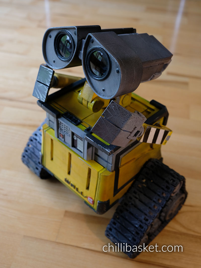
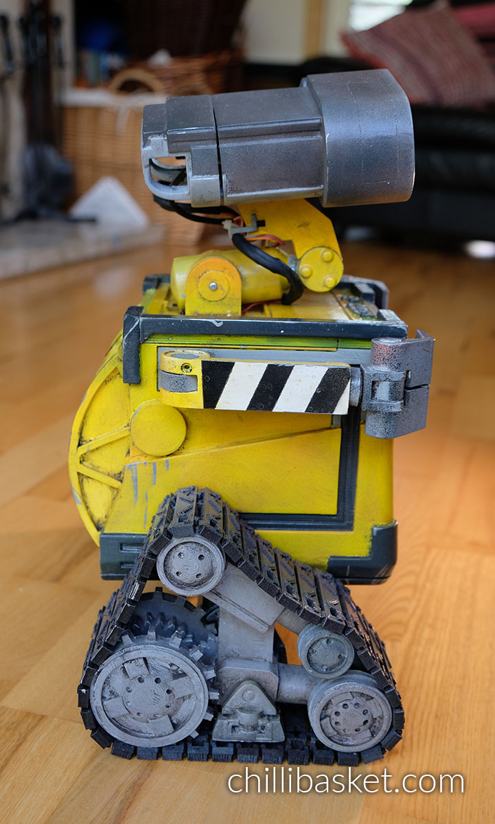
Few robots are more recognisable than WALL·E; his cute appearance and distinctive personality make him instantly endearing to anyone who sees him! In this project, I designed a WALL·E replica with the aim to allow each of the robot’s joints to be moveable by hand or using servo motors.
Loosely based on the dimensions and design of ChaosCoreTech’s Wall-E replica, this version was designed from scratch in Solidworks and allows 7 of the joints to be actuated, including the arms, neck, head and eyes. The robot design has the following features:
- Each eye can be raised and lowered independently with servo motors.
- There is room in each eye to add a small camera.
- The head can look left and right using a servo motor.
- The neck is actuated at two joints, allowing the head to look up/down and to be raised/lowered.
- Each arm has a motor at the shoulder to move it up/down.
- The arms consist of pressure fit joints, hands and fingers, which can be manually posed.
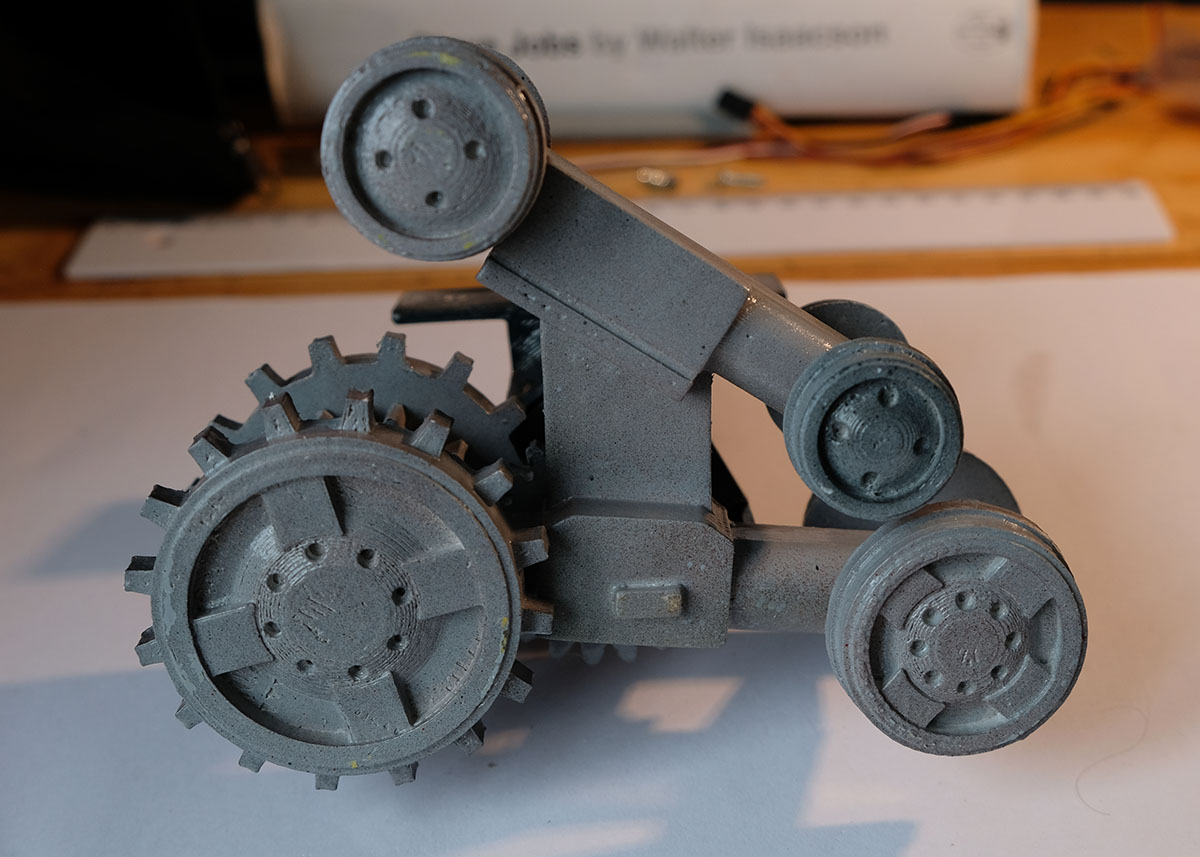
- The tank treads (skid steering) are fully 3D printed and can be powered using two 12V DC geared motors.
This is an ambitious project, aimed at people who want to build a fully animatronic WALL·E robot with servo controlled joints. It took me about 3 months to design and assemble the robot, with more than a month spent on just 3D printing all of the parts. In total, there are 310 parts (although 210 of those are very small and make up the tank treads).
1. List of 3D Printed Parts
[a] Original Design
The robot comprises of 310 individual parts, so this definitely is not an easy project suitable for people who don’t have much experience with 3D printing! Personally, I spent more than a month printing all the parts, with the printer running almost every day. The largest components (the main body parts) took up to 14 hours of print time each, while the smaller parts took 5-6 hours. If you are interested in making your own robot, I have uploaded the 3D files for all the components on Thingiverse.
If you want to jump straight into 3D printing, the *.STL files are available here:
If you want to modify the files in CAD, I’ve also exported the files in the *.STEP format:
Finally, a PDF file containing a list of all of the components required can be found here:
[b] Remixes by other Makers
Since I first released my original Wall-E design, a variety of other makers have built their own robots and made tweaks and improvements to the design. Before you start printing my design, I would encourage you to check out a few of these remixes to see if you want to use them as well:
- Track/drive Improvements
- Head/neck Improvements
- Improved head & neck, using bolts instead of glue by rene1960
- Replacement for paperclip linkage arms by ZDC (recommended)
- Motorised eyebrows by DaddieMon – note this might prevent a camera from fitting into the eyes
- Movie Accuracy Improvements
- Additional Parts
I haven’t had a chance to print any of these remixes myself, so if you come across any issues with the remix designs you will need to contact the authors of those parts directly. Click here to view all available remixes on Thingiverse.
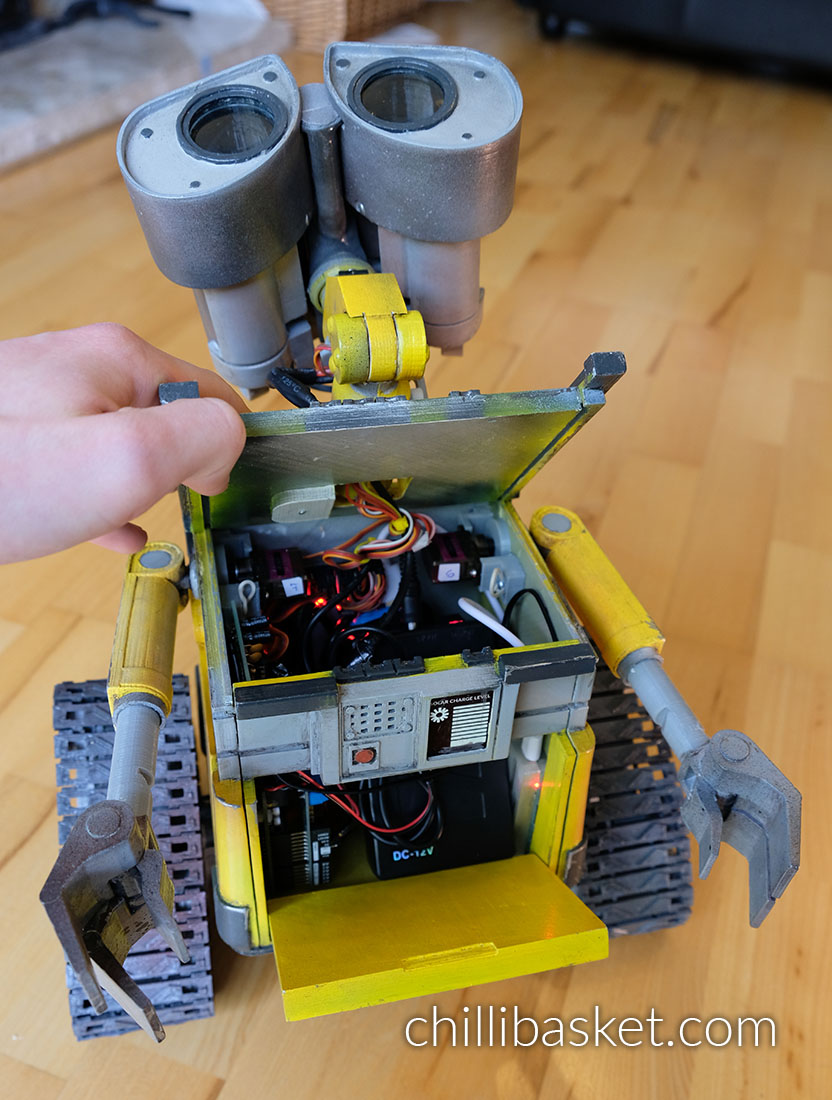
2. List of other Components
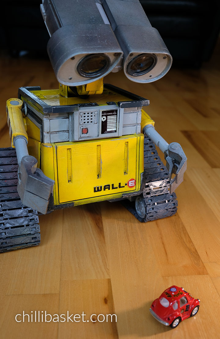
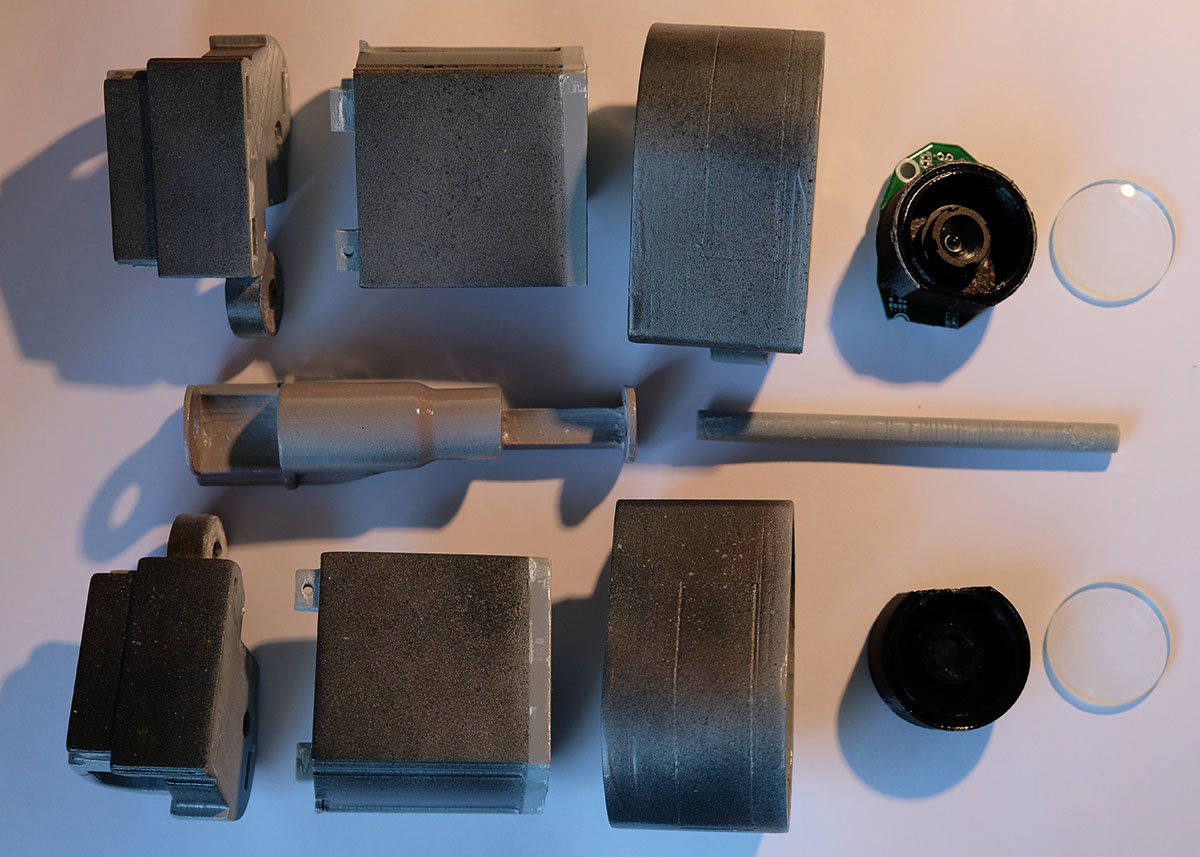
A variety of other hardware is used to fasten the 3D printed parts together and bring the robot to life. A list of the hardware and electronic parts that I used is shown below. To make WALL·E look more realistic, I took apart some old binoculars and used the lenses as the eyes. I think that the shine and reflections on the glass adds a lot of soul to the robot, and make him look even cuter.
- Hardware
- M3 Bolt (10mm length) – x14
- M3 Bolt (20mm length) – x12
- M3 Bolt (6mm length) – x2
- M3 Nut – x26
- Paper clips (used for linkages) – x3
- Plano-convex lens for the eyes (between ⌀31.5-32.5mm) – x2
- Electronics
- High Torque Micro Servo Motor – x7
- 12V DC Geared Motor (100-150RPM, ⌀37mm, off-center output shaft) – x2
- Arduino Uno (or equivalent) – x1
- Motor Controller Shield – x1
- i2c Servo Controller Board – x1
- 12V DC Battery Pack – x1 For example:
- 12V to 5V DC Buck Converter – x1
- Raspberry Pi – x1
- (optional) USB Camera – x1
- (optional) Small Speaker – x1
Note: Links are for reference only, and are not where I bought my parts. Please shop around to find the best supplier near you! The DC geared motors can also be bought with additional encoders, allowing you to have better control of the robot’s movement speed. However, if you want to add encoders you will need to modify my Arduino code in order to support them; an intermediate level of programming knowledge is required!
While it is possible to use a Wifi/bluetooth connected Arduino micro-controller to control the robot, I decided to use a Raspberry Pi instead. Since the Raspberry Pi is essentially a small computer, it can be used to play sound effects, stream the video from a USB camera, and host a web interface through which the robot can be controlled.
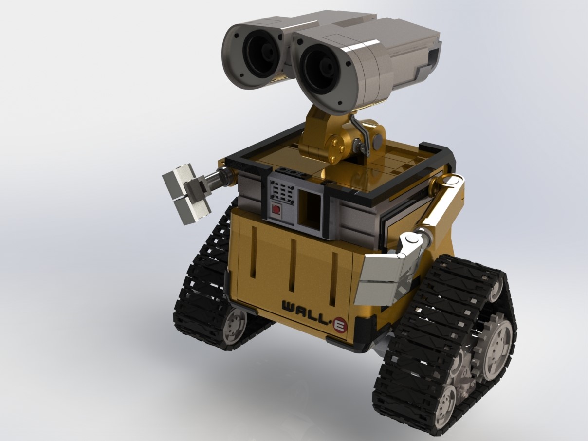
3. 3D Design and Printing
I designed all the components in Solidworks, using images and other 3D models as reference. The main aim in the design process was to split the robot into small enough pieces so that they would fit into the 3D printer, and also to integrate all the motors and electronic components. I tried to make the robot as small as possible, while still leaving enough room for the motors.


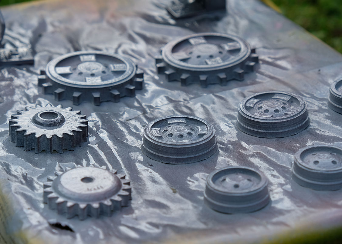
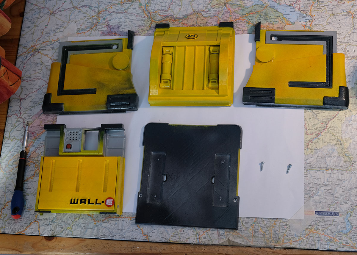
4. Painting
After 3D printing each of the parts, I spent a lot of time sanding the parts to remove all of the print lines and give them a smooth finish. Two coats of filler-primer were then applied, with more sanding done between each of the coats. Using a primer is important, as it helps the paint to stick to the plastic and not rub off as easily. It is also useful as it makes imperfections and bumps on the part more obvious, showing where further sanding needs to be done.
Each of the parts was then individually painted with lacquer spray paints. I only used yellow, white, light grey, dark grey, black, and red spray paints to paint the whole robot. By splattering light layers of black and red paint onto the parts that were painted grey, it was possible to add texture and make them look a lot more like real metal.
Finally, after fully assembling the robot, I used black and brown acrylic paints to weather the robot. This involves applying the paint liberally onto all the surfaces, and roughly wiping away most of it with a towel. The paint that isn’t wiped away stays in the corners and crevices of the parts, making the overall replica look older and more realistic.

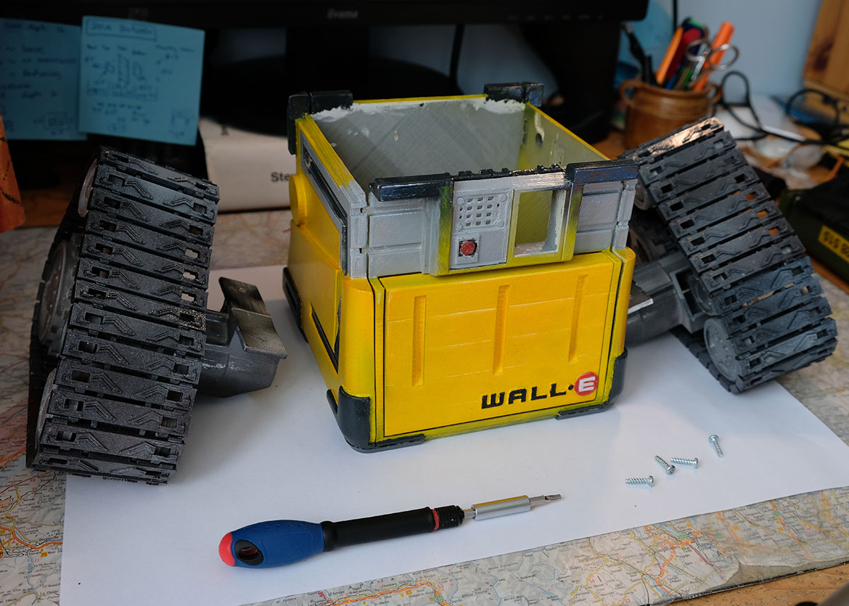
5. Assembly
The video below shows how to assemble the robot. Overall, the assembly is not too difficult, but it is important to put the parts together in the right order. While a couple of small parts needs to be glued together, most parts are fastened together using bolts. This makes assembly and disassembly easy if any parts need to be fixed or replaced. The trickiest part was probably the wiring, figuring out how to connect the motors in the eyes of the robot to the controller in the body.

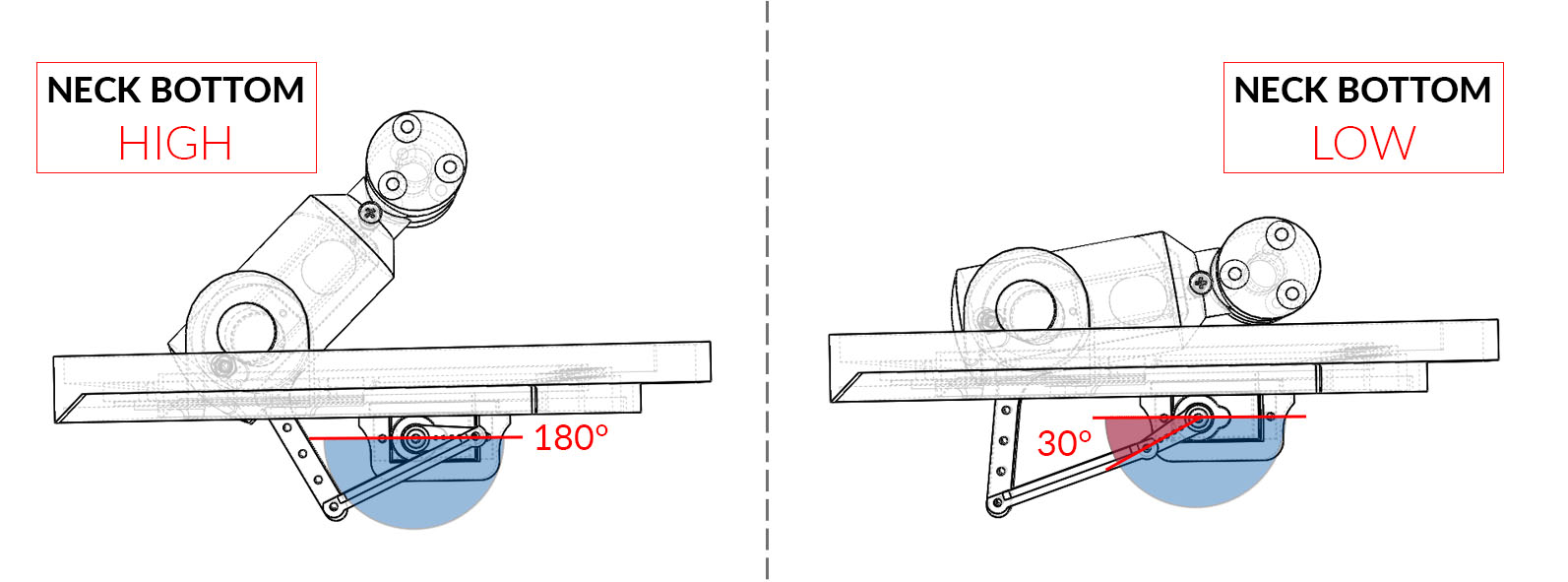
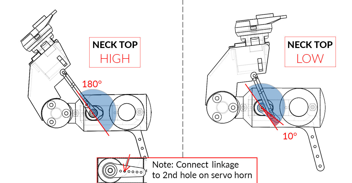
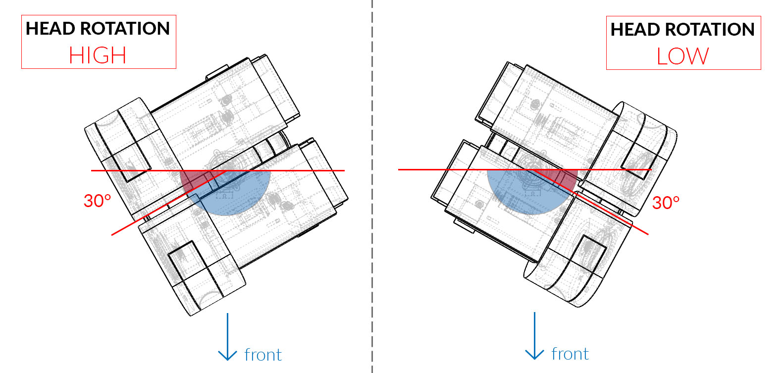
IMPORTANT: Before attaching the servo motors, you need to make sure that the angle of the motor is correct. Since the servos can only rotate 180 degrees, you won’t be able to control the joint correctly if they are attached when positioned at the wrong angle. Diagrams showing the correct angles of each of the servo motors are shown below. To attach the servo, first rotate the output shaft clockwise as far as it will go; this gives you the min/max position of the servo. Then attach the servo horn onto the output shaft at the correct angle, as shown in the diagrams. Minor variances in the positioning of the servo horn will be corrected in the servo calibration step in section 8[c].


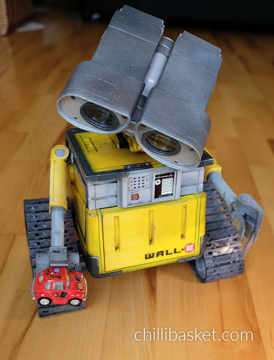
In the 3D printed design of the robot, I have left a gap where Wall-E’s “Solar Charge Panel” indicator should go. I purposefully left the gap so that I could add some lights or a screen there later which would show the actual battery level of the robot. To provisionally fill the space (as seen in my images of the robot), I printed out a picture of the panel on some gloss photo paper and taped it into the space. Here is a PDF of the panel I used; it is already at the correct size, just make sure when sending it to the printer to turn off scaling (print at “actual size”):
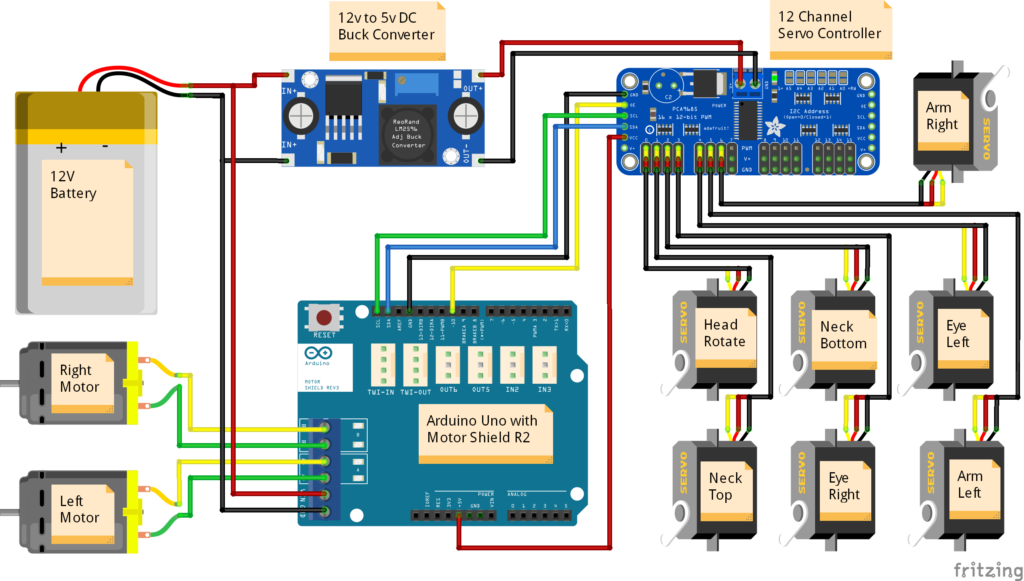
6. Wiring and Electronics
The wiring diagram is shown below, illustrating how each of the electronic components were connected in the robot. The USB port of the Arduino Uno was then connected to the USB port of the Raspberry Pi. If the 12v to 5v DC buck converter is capable of delivering up to 5 amps, then the Raspberry Pi can be directly powered from the converter. Otherwise, it should be connected to a separate 5v battery.
7. Programming
The programming of the robot can be split into two main parts; the code for the Arduino micro-controller, and the web-server on the Raspberry Pi. I’ve uploaded all my code onto GitHub; the link is shown below.
The Arduino controls all of the motors within the robot, determining how they should move. In the code I added a velocity controller, so that the servo motors don’t suddenly jump into life at full speed, but instead start and stop gently.
The Raspberry Pi is connected to the Arduino via a USB cable, and can send user commands to the Arduino to make the robot move in a specific way. The Pi is also supports a USB webcam and a speaker, and can play sound effects. The code is written in Python, and uses ‘Flask’ to generate a web-server. Any computer on the same local network can then access the page and remote control the robot.
8. Arduino Installation Guide
[a] Basic Installation
- Ensure that the wiring of the electronics matches the circuit diagram.
- Download/clone the folder “wall-e” from the GitHub repository.
- To get all the files from the repository, click on the green Code button on the top-right of the page.
- Click on Download ZIP. Once the files have downloaded, extract the zip folder.
- To upload the code to the Arduino, you need to download the Arduino IDE from the official website.
- Open wall-e.ino in the Arduino IDE; the files MotorController.hpp and Queue.hpp should automatically open on separate tabs of the IDE as well.
- Install the Adafruit_PWMServoDriver.h library
- Go to Sketch -> Include Library -> Manage Libraries…
- Search for Adafruit PWM Servo Driver.
- Install latest version of the library.
- Connect to the computer to the micro-controller with a USB cable. Ensure that the correct Board and Port are selected in the Tools menu.
- Upload the sketch to the micro-controller.
[b] Testing the Main Program
- Once the sketch has been uploaded to the Arduino, power on the 12V battery while the micro-controller is still connected to the computer.
- Open the Serial Monitor (button in top-right of Arduino IDE). Set the baud rate to 115200.
- To control the movement of the robot, send the characters ‘w’, ‘a’, ‘s’ or ‘d’ to move forward, left, back or right respectively. Send ‘q’ to stop all movement.
- To move the head, send the characters ‘j’, ‘l’, ‘i’ or ‘k’ to tilt the head left or right and the eyes upwards or downwards. At this stage, the servos may try to move further than they should and may look uncoordinated. This will be solved by performing the servo motor calibration steps below.
[c] Servo Motor Calibration
- Download/clone the folder “wall-e_calibration” from the GitHub repository.
- Open wall-e_calibration.ino in the Arduino IDE.
- Upload the sketch to the micro-controller, and open the serial monitor and set the baud rate to 115200.
- The sketch is used to calibrate the maximum and minimum PWM pulse lengths required to move each servo motor across its desired range of motion. The standard LOW and HIGH positions of each of the servos is shown in the images below.
- When starting the sketch and opening the serial monitor, a message should appear after 2-3 seconds, saying that it is ready to calibrate the LOW position of the first servo motor (the head rotation).
- Send the character ‘a’ and ‘d’ to move the motor backwards and forwards by -10 and +10. For finer control, use the characters ‘z’ and ‘c’ to move the motor by -1 and +1.
- Once the motor is position in the correct position (as shown in the images below), send the character ‘n’ to proceed to the calibration step. It will move on to the HIGH position of the same servo, after which the process will repeat for each of the 7 servos in the robot.
- When all joints are calibrated, the sketch will output an array containing the calibration values to the serial monitor.
- Copy the array, and paste it into lines 144 to 150 of the program wall-e.ino. The array should look similar to this:
int preset[][2] =  {{410,120},  // head rotation
                    {532,178},  // neck top
                    {120,310},  // neck bottom
                    {465,271},  // eye right
                    {278,479},  // eye left
                    {340,135},  // arm left
                    {150,360}}; // arm right
[d] Battery Level Detection (optional)
When using batteries to power the robot, it is important to keep track of how much power is left. Some batteries may break if they are over-discharged, and the SD card of the Raspberry Pi may become corrupted if not enough power is delivered.
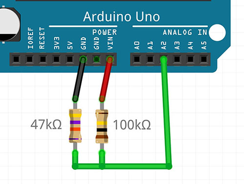
- To use the battery level detection feature on the Arduino, connect the following resistors and wiring as shown in the image below. The resistors (potential divider) reduce the 12V voltage down to a value below 5V, which is safe for the Arduino to measure using its analogue pins. The recommended resistor values are
R1 = 100kΩandR2 = 47kΩ. - Uncomment line 54 in the main Arduino sketch wall-e.ino.
- If you are using different resistor values, change the value of the potential divider gain factor on line 54 of the sketch, according to the formula:
POT_DIV = R2 / (R1 + R2). - The program should now automatically check the battery level every 10 seconds, and this level will be shown on the Raspberry Pi web-interface in the “Status” section.
[e] oLed Display (Optional) (Contributed by: hpkevertje)
It is possible to integrate a small 1.3 inch oLED display which will show the battery level of the robot on the front battery indicator panel. This feature requires the battery level detection circuit in the previous section to be enabled, and the screen will update every time the battery level is calculated. This function uses the u8g2 display library in page mode; on the Arduino UNO you may get a warning that the memory usage is high, but this warning can be ignored.
- To use the oLed display feature on the Arduino, connect an i2c oLed display on the i2c bus on the servo motor module (see diagram).
- Install the U8g2 library in the Arduino library manager:
- Go to Sketch -> Include Library -> Manage Libraries…
- Search for U8gt. The library publisher is “oliver”.
- Install latest version of the library.
- Uncomment line 74
#define OLEDin the main Arduino sketch wall-e.ino. - If you are using a different display that is supported by the library, you can change the constructor on line 78 as documented on the library reference page. The default is for an SH1106_128X64_NONAME display.

[f] Adding your own Servo Animations (optional)
My code comes with two animations which replicate scenes from the movie; the eye movement Wall-E does when booting-up, and a sequence of motions as Wall-E inquisitively looks around. From code version 2.7 and onwards, I’ve now made it easier to add your own servo motor animations so that you can make your Wall-E do other movements…
- Open up the file
animations.ino, which is located in the same folder as the main Arduino sketch. - Each animation command consists of the positions you want each of the servo motors to move to, and the amount of time the animation should wait until moving on to the next instruction.
- You can add a new animation by inserting an extra
casesection into the switch statement. You should slot your extra code into the space above thedefaultsection. - The time needs to be a number in milliseconds (for example, 3.5 seconds = 3500)
- The servo motor position commands need to be an integer number between 0 to 100, where
0 = LOWand100 = HIGHservo position as calibrated in thewall-e_calibration.inosketch. - If you want to disable a motor for a specific move, you can use -1.
- For example:
case 3:
        // --- Title of your new motion sequence ---
        //          time,head,necT,necB,eyeR,eyeL,armL,armR
        queue.push({  12,  48,  40,   0,  35,  45,  60,  59});
        queue.push({1500,  48,  40,  20, 100,   0,  80,  80});
        // Add as many additional movements here as you need to complete the animation
        // queue.push({time, head rotation, neck top, neck bottom, eye right, eye left, arm left, arm right});
        break;
You can then add the animation the animation to the Raspberry Pi web-interface with the following steps:
- Edit the HTML file on the Raspberry Pi using the command:
nano ~/walle-replica/web_interface/templates/index.html - On lines 245 to 247 you can see the buttons relating to the 3 default animations. To add your own animations, simply copy/paste an extra line to the bottom of the list, changing the following items:
- Insert the number of the CASE statement relating to the animation, for example
file-name="3" - Insert the length of the entire animation in seconds, for example
file-length="21.5" - Update the “on-click” parameter with the same numbers:
on-click="anime(3,21.5)" - Add the name of the animation, for example
Dance Sequence
- Insert the number of the CASE statement relating to the animation, for example
- This would give you a line looking like the code below. Press
CTRL+Oto save andCTRL+Xto exit the editor.
<a href="#" class="list-group-item list-group-item-action" file-name="3" file-length="21.5" onclick="anime(3,21.5)">Dance Sequence <i class="entry-time"> | 21.5s</i></a>
9. Raspberry Pi Web Server
[a] Hardware Setup
- Connect the power cable of the Raspberry Pi to the USB power output port on the 12V to 5V buck converter.
- Connect the USB data cable from the Arduino to the Raspberry Pi.
- If you have a Raspberry Pi camera, plug the ribbon cable into the CSI camera connector.
- For setup and installation, you can plug in a monitor into the HDMI port and a USB keyboard and mouse. Alternatively you can connect to and configure the Raspberry Pi from a different computer using SSH.
[b] Basic Installation
- Setup the Raspberry Pi to run the latest version of Raspberry Pi OS Desktop. The setup instructions can be found on the Raspberry Pi website. Make sure that the Raspberry Pi is connected to the internet.
- Open the “Terminal” command line on the Raspberry Pi.
- Clone repository into the home directory of the Raspberry Pi:
cd ~
git clone https://github.com/chillibasket/walle-replica.git
Note
You can configure the web-interface settings by editing the “config.py” file:
- Open the config file:
nano ~/walle-replica/web_interface/config.py- On line 14 you can change the password for the web interface. The default password is “walle”
- On line 15 the default serial port which is used to connect to the Arduino can be set. You can find a list of all the connected serial ports using the
dmseg | grep ttycommand.- On lines 16 and 17 you can configure whether the Arduino and camera should automatically connect when starting up the web server.
-
Once you have finished editing the configurations, run the installation script which sets up all the required libraries for you (note – this may take some time to complete):
cd ~/walle-replica
sudo chmod +x ./raspi-setup.sh
sudo ./raspi-setup.sh
[c] Using the Web Server
- If the installation completed successfully, the webserver should start automatically when the Raspberry Pi is powered on. This is done using a Systemd service.
- On the Raspberry Pi you can view the web interface from the browser at http://localhost:5000
- To view the interface from a different computer on the same WiFi network, you first need to determine the current IP address of the Raspberry Pi on your network using the command:
hostname -I - To access the web interface, open a browser on any computer/device on the same network and type in the IP address of the Raspberry Pi, follow by
:5000. For example192.168.1.10:5000 - To start controlling the robot, you first need to make sure that the serial communication with the Arduino has started. To do this, go to the
Settingstab of the web-interface, select the correct serial port from the drop-down list and press on theReconnectbutton. If the configurations were set up correctly, this should happen automatically.
Tip
Here are some useful commands to control the web interface:
- To stop the automatic web interface service:
sudo systemd stop walle.service- To disable start on boot:
sudo systemd disable walle.service- To reenable start on boot:
sudo systemd enable walle.service- To start the service after it has been stopped:
sudo systemd start walle.service- View the status of the service and check for errors:
sudo systemd status walle.service- If you want to manually run the web server from the terminal, for example to check for errors:
python3 ~/walle-replica/web_interface/app.py. You can then pressCTRL + Cto stop the web server again.
[d] Controlling the Robot using Blocky (Contributed by: dkrey)
Since version 3.0, a new tab has been added to the web interface where the robot can be controlled using a drag-and-drop scripting language. Simply drag the actions you want to perform from the left sidebar and drop them into the editor area. For example you can drive Wall-E, move the actuators, and play audio sounds. This is a great way for kids to learn the basics of programming while having fun!
For the commands which drive the motors, you may need to tune the parameters at the bottom of the “config.py” file on lines 25 to 28 to make sure that the speed and turning amount is correct.
[e] Adding a Camera Stream (optional)
The web server automatically supports any camera which connects to the CSI connector on the Raspberry Pi with a ribbon cable. Unfortunately USB web cameras are not supported by this system, but I hope to add support for them again in the future.
[f] Adding new Sounds (optional)
- By default the Raspberry should automatically select whether to output audio to the HDMI port or the headphone jack. However, you can ensure that it always uses the headphone jack with the following command:
amixer cset numid=3 1 - Make sure that all the sound files you want to use are of type
*.wav. Most music/sound editors should be able to convert the sound file to this format. - Change the file name so that it has the following format:
[group name]_[file name]_[length in milliseconds].wav. For example:voice_eva_1200.wav. In the web-interface, the audio files will be grouped using the “group name” and sorted alphabetically. - Upload the sound file to Raspberry Pi in the following folder:
~/walle-replica/web_interface/static/sounds/ - All the files should appear in the web interface when you reload the page. If the files do not appear, you may need to change the privileges required to access the folder:
sudo chmod -R 755 ~/walle-replica/web_interface/static/sounds
[f] Set up Raspberry Pi as a WiFi Hotspot (optional)
If you would like to control the robot outdoors or at conventions, there may not be any safe WiFi networks you can connect to. To overcome this issue and eliminate the need for any external networking equipment, the Raspberry Pi can broadcast its own WiFi network. You can then connect the computer/phone/tablet you are using to control the robot directly to this network.
To set up the WiFi hotspot, we will use the RaspAP project which takes care of all the configuration and tools to get the system working. The following instructions are based on their quick installation guide:
- Update Raspian, the kernel and firmware (and then reboot):
sudo apt-get update sudo apt-get dist-upgrade sudo reboot - Ensure that you have set the correct WiFi country in raspi-config’s Localisation Options:
sudo raspi-config - Run the quick installer:
curl -sL https://install.raspap.com | bash- For the first few yes/no prompts which will appear during the install, type “y” (yes) to accept all of the recommended settings. The final two prompts (Ad Blocking and the next one) are not required so you can type “n” (no) for those.
- Reboot the Raspberry Pi again to implement the changes:
sudo reboot - Now the Raspberry Pi should be broadcasting a WiFi network with the following details:
- SSID (wifi name):
raspi-webgui - Password:
ChangeMe
- SSID (wifi name):
- After connecting to the WiFi network from a your computer, phone or tablet, the Wall-E web-interface can be opened by typing this address into your browser:
http://10.3.141.1:5000 - (Recommended) To change the WiFi name and password, go to the WiFi configuration webpage at:
http://10.3.141.1. The default username isadminand password issecret.- Click on “Hotspot” in the left sidebar. In the “Basic” tab you can change the WiFi network name, while the WiFi password can be changed in the “Security” tab.
- To change the admin password for the interface used to manage the WiFi settings, click on the “Admin” icon in the top-right of the interface.
Recent Updates/Edits:
- 9th June 2024 – updated to reflect new code changes as part of release v3.0
- 8th August 2020 – to reflect latest updates in the Arduino Code
- 18th September 2020 – Updated RPi setup instructions to use python3
- 28th October 2020 – Removed “serial” library from install command since it is not needed and conflicts with “pyserial”
- 2nd November 2020 – Added section with links to other remixes
- 16th November 2020 – Instructions of how to add animations to the web-interface
- 19th December 2020 – Changed instructions of how to set up a WiFi hotspot
- 29th May 2021 – Added oLED display instructions
- 22nd May 2022 – Updated instructions to include all code required or setting up camera stream