Amplifiers are devices which take in an input electrical signal and increase the amplitude (voltage) of that waveform. In music systems, these signals are usually audio and amplifying them increases the volume of the signal. However, Operational Amplifiers (op. amps) are a special type of amplifier which take in two inputs rather than one, and amplify the difference between both signals. By using some simple circuit designs, it is possible to apply these amplifiers to perform many additional tasks, such as inverting the signal, adding up multiple signals, and isolating signals from the rest of the circuit. This wide range of applications is why operational amplifiers are so commonly used in modular synthesisers designs. In this tutorial, I briefly cover how op. amps works and discuss the most common op. amp circuits used in modular synths.
1. How do Operational Amplifiers Work?
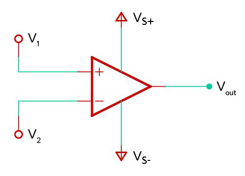
Operational amplifiers are a type of integrated circuit designed to amplify the difference in voltage between the two input signals. Mathematically, the output signal (Vo) of an op. amp is proportional to the difference between the voltages being supplied to the positive (V+) input terminal and the negative (V–) input terminal:
V_o =A_{vo}(V_+-V_-)The open loop gain (Avo) refers to the amount of amplification applied to the difference between the two inputs. One characteristic that makes op. amps so useful is that the open loop gain/amplification value is very large (often around x100,000); this allows the output voltage to be regulated down to any desired value using some simple external components. The table below lists the main characteristics of operational amplifiers, and compares the ideal versus the actual characteristics seen in practice:
| Ideal | Actual |
|---|---|
| The amplifier has an infinitely large open loop gain | The gain is large but finite (typically 100’s dB) |
| The input impedance is infinitely large (no current flows through the inputs) | The input impedance is high but finite (typically 100’s MΩ); a small current flows into the inputs |
| There is zero output impedance | The output impedance is low, but not zero (typically 10’s Ω) |
| The gain is not dependent on the frequency of the input signals | The signal bandwidth is not infinite and at higher frequencies the gain tends to reduce |
| The amplifier can switch the output voltage instantaneously to changes in the inputs | The speed at which the output voltage can change is limited and is defined by the “slew rate” |
| The output voltage can increase up to the voltages supplied to the power rails of the amplifier | There is a voltage drop introduced, meaning the output cannot increase up to the rails (usually 2-3 V drop) |
In practice, while op. amps don’t exactly follow the ideal assumptions, they are close enough so that these mathematical simplifications can usually be used when designing modular synthesiser circuits and figuring out suitable component values. Some of the situations when you need to watch out for non-ideal properties of op. amps are:
- The resistance of the input signals is very high
- The output load from the circuit is very low
- High frequency operation is required
- The output voltage needs to be able to swing right up to the supply voltages
In applications such as these, there are many specialised types of operational amplifiers which can fulfil these needs (but often are more expensive or make a compromise with other properties of the amplifier).
Operational Amplifiers: Further Reading
- Great video explaining how op. amps work: EEV Blog – OpAmps Tutorial
2. Voltage Comparator (Threshold Detection)
A comparator is a type of circuit which compares the voltages of two inputs, outputting a high voltage value when input 1 is larger than input 2, and a low value when input 1 is smaller than input 2. If the voltage of the second input remains fixed, a comparator circuit can be used to determine if the first input signal has exceeded the voltage threshold of the second signal.
(a) Simple Comparator
An op. amp can be used as a simple comparator circuit by connecting the two signals you want to compare to the inverting (V2) and non-inverting (V1) input terminals. If the voltage at the non-inverting input is greater than the one at the inverting input, then the output voltage will be positive; otherwise the output will be negative.
Due to the high gain of the amplifier, the output will saturate almost immediately to the maximum voltage which the op. amp can supply — this is dictated by the supply voltage rails. As a result, the output appears to be almost digital, switching between a fixed low and high voltage value.
Mathematical Derivation
- Starting with the op. amp formula:
V_{out} = A_{vo}(V_1 - V_2)- If the gain is very large (approaching infinity), this means the output should also approach positive or negative infinity; however, the maximum output voltage is limited by the supply voltages connected to the amplifier:
\textbf{If: } \; A_{vo} \to \infin \quad \textbf{ Then:}V_{out}=\begin{cases}
V_{s+} -V_{d} & V_1 > V_2 \\
V_{s-} +V_{d} & V_1 < V_2 \\
\text{Unstable} & V_1 = V_2
\end{cases}Depending on whether the difference between the two input terminals is positive or negative, the output will jump to equal the positive or negative supply rails. When both inputs are equal, the output is unstable and can quickly jump between both rails. Note that the voltage of the output is reduced by the term Vd since most op. amps (unless advertised) introduce a voltage drop of up to 2 to 3 volts with respect to the rails.
(b) Inverting Comparator with Hysteresis
In the above simple comparator circuit, when both input voltages are equal the output voltage can jump rapidly between both input rails. This can be an issue when the input signal itself is noisy; in that case the output jumps back and forth multiple times as the input voltage approaches the reference voltage instead of just giving a single clean transition. The most common method of dealing with this issue is to use positive feedback to offset the reference voltage after a transition has occurred. As a result, the reference voltage as the signal is increasing is different than that when the signal is decreasing (this is known as hysteresis).
Mathematical Formula
The voltage at the non-inverting terminal changes depending on whether the output voltage is currently at the high or the low voltage level. This means that the voltage threshold changes depending on whether the input signal is rising or falling.
For rising input voltages we can calculate the voltage at the non-inverting input (the threshold voltage) using superposition:
V_{+rising} = \frac{V_{ref}(R_1)}{(R_1+R_2)}+\frac{V_{outLOW}(R_2)}{(R_1+R_2)}\therefore V_{+rising} = \frac{(V_{ref}R_1+V_{outLOW}R_2)}{R_1+R_2}Similarly, for falling input voltages the threshold can be calculated:
\therefore V_{+falling} = \frac{(V_{ref}R_1+V_{outHIGH}R_2)}{R_1+R_2}So the total hysteresis voltage swing can be calculated by subtracting these two thresholds:
V_{hysteresis} = V_{-rising}-V_{+falling}\therefore V_{hysteresis} = (V_{outHIGH}-V_{outLOW})\frac{R_2}{R_1+R_2}Circuit Diagram
In this circuit configuration, the output voltage is high if the input voltage is below the lower “falling” threshold, and it switches to a low output voltage when the input voltage exceeds the upper “rising” threshold. When the input voltage is in-between those two thresholds, it stays at whatever level it was at before:
V_{out}=\begin{cases}
V_{s+} -V_{d} & V_{in} < V_{+falling} \\
V_{s-} +V_{d} & V_{in} > V_{+rising} \\
\text{Unchanged} & V_{+rising} \le V_{in} \le V_{+falling}
\end{cases}
3. Unity Gain Amplifier (Signal Buffer)
In a unity gain amplifier (also known as a signal buffer or a voltage follower), the output of the op. amp is connected back into the inverting input terminal. Using this feedback, the amplifier actively tries to reduce the difference between the input and output voltages, making them the same. This circuit is very common, as it can be used to electrically isolate (buffer) two parts of a circuit. The output of the op. amp acts as an ideal voltage source, meaning the load connected to the output won’t affect the signal at the input of the op. amp and vice versa.
Mathematical Derivation
- Starting with the op. amp formula:
V_{out}=A_{vo}(V_{in}-V_{out})- Rearranging:
(A_{vo}+1)V_{out}=A_{vo}V_{in}- Due to the large open-loop gain of the amplifier (which is much larger than one), the left side of the equation can be simplified to remove the “+ 1” term.
\textbf{If: } \; A_{vo} \gg 1 \quad \textbf{ Then: } \; A_{vo}+1 \approx A_{vo}\therefore \; V_{out} = V_{in}Circuit Diagram

4. Simple Amplifier (Signal Boost)
(a) Inverting Amplifier
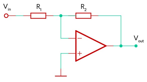
An amplifier circuit is a system which takes an input signal and increases the magnitude (amplitude) of that signal. For example in modular synthesisers, this would increase the volume of the audio waveform. An inverting amplifier configuration applies this increase and inverts the signal, meaning that the positive sections of the signal become negative and the negative sections become positive.
Mathematical Derivation
- To start off, we will substitute in zero for the non-inverting input terminal which is connected to ground:
V_{out}=A_{vo}(V_+-V_-)\textbf{Since: } \; V_+=0 \quad \Rightarrow \; V_{out} = A_{vo}(-V_-)- Due to the high open-loop gain, the amplifier changes its output to try to keep the voltages of the inverting and non-inverting input terminals the same. This creates a “virtual ground” at the negative input.
\textbf{If: } \; A_{vo} \to \infin \quad \textbf{ Then: } \; V_- \to 0- Using superposition we can derive another formula for the voltage at the inverting input (see explanation in box below):
V_-= \frac{V_{in}R_2}{R_1+R_2}+\frac{V_{out}R_1}{R_1+R_2} = 0- This can be rearranged and simplified to give us the relationship between the input and output voltages:
V_{in}R_2+V_{out}R_1 = 0\therefore \: V_{out}=-V_{in}\frac{R_2}{R_1}Circuit Diagram
Superposition
When trying to calculate the voltage at a junction between multiple branches of a circuit, a useful trick is to look at the voltage contribution of each branch of the circuit separately before adding all the contributions together. When calculating each branch, all of the voltages at the other branches are set to zero. This process is known as “superposition” and is used extensively in circuit analysis.
(b) Non-inverting Amplifier
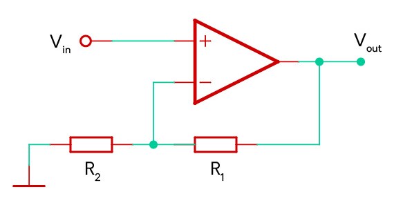
The non-inverting amplifier configuration is almost identical to the inverting amplifier above, except that the ground and input voltages are swapped. By adjusting the ratios of the two feedback resistors R1 and R2 the amount of gain/amplification of the circuit can be controlled.
Mathematical Derivation
- If the open loop gain is infinitely large, then the voltages at the inverting and non-inverting inputs needs to be equal:
V_{out}=A_{vo}(V_{in}-V_-)\textbf{If: } \; A_{vo} \to \infin \quad \textbf{ Then: } \; V_{in} - V_- \to 0\therefore V_{in} = V_-- Using the formula for a potential divider, the voltage at the inverting input terminal can be related to the output voltage:
V_- = \frac{V_{out}R_2}{R_1+R_2}- Rearranging to isolate the output voltage:
\therefore V_{out}=V_{in}\left( \frac{R_1}{R_2} + 1 \right)Circuit Diagram
5. Summing Amplifier (Signal Mixer)
(a) Inverting Summing Amplifier
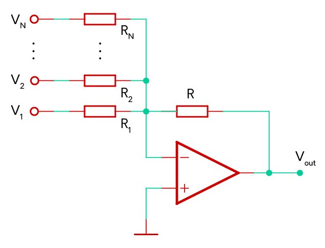
In modular synths you often want to add multiple signals together to create a variety of effects and harmonies. This can be done very simply by adding additional inputs to the normal inverting amplifier I described in Section 3(a). The contribution of each input signal to the output is dependent on the ratio of the input and feedback resistors.
Mathematical Derivation
V_{out}=A_{vo}(V_+-V_-) = A_{vo}(-V_-)\textbf{If: } \; A_{vo} \to \infin \quad \textbf{ Then: } \; V_- = 0- Since almost no current flows into the inverting op. amp input, the sum of all the current coming into the inputs needs to flow through the feedback resistor (R). Note that as the conventional current flows from the 0V point at the inverting input across the feedback resistor, this can only be true if the output is at a lower voltage (meaning it is negative).
I_R=\sum_{i=1}^N\frac{V_i}{R_i} \quad \textbf{ and } \quad V_{out}=-I_RRV_{out}=-\left(V_1\frac{R}{R_1}+V_2\frac{R}{R_2}+...+V_N\frac{R}{R_N}\right)- If all the resistors are equal, then all the resistor terms in the equation cancel each other out and the op. amp simply sums all the input voltages together and inverts it:
\textbf{If: } \; \{R_i = R \text{ }| \text{ } i = 1,...,N\}\therefore V_{out} = -(V_1 + V_2 + ... + V_N)Circuit Diagram
(b) Non-inverting Summing Amplifier
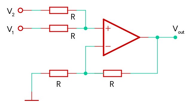
It is also possible to create a non-inverting signal mixer, where the output is the positive sum of the inputs. However, this circuit is not as common in synthesisers since it is not as easy to add additional inputs. If more than two inputs are added, the ratio of the two resistors connected to the inverting input of the op. amp needs to be changed to ensure the output gain factor remains the same.
Mathematical Derivation
V_{out}=A_{vo}(V_+-V_-)\textbf{If: } \; A_{vo} \to \infin \quad \textbf{ Then: } \; V_+ = V_-- Same as the non-inverting amplifier circuit (4b), the voltage of the inverting input can be calculated using the potential divider formula.
V_-=\frac{V_{out}R}{R+R}=\frac{V_{out}}{2}- The voltage at the non-inverting input can be calculated using superposition:
V_+=\frac{V_1R}{R+R}+\frac{V_2R}{R+R}=\frac{V_1+V_2}{2}- Since the voltage at the inverting and non-inverting inputs needs to be equal, the output voltage therefore is the sum of the two inputs:
\therefore V_{out}=V_1+V_2Circuit Diagram
6. Dealing with Unused Op. Amps
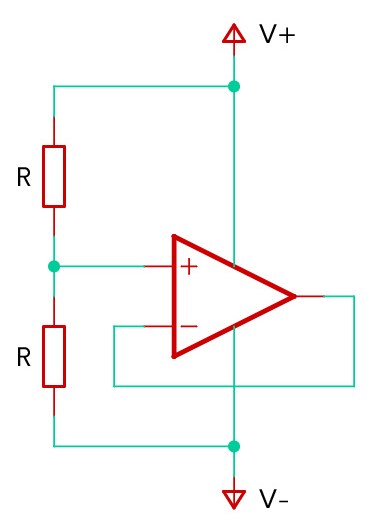
When working with operational amplifiers on a breadboard or in a circuit, each IC chip usually contains multiple op. amps. Commonly chips contains either 2 or 4 amplifiers; however, your circuit may not need to use all of these amplifiers meaning that one or two of them will remain disconnected. In this situation it is good practice to connect the pins of the unused amplifiers to a known input and output so that they won’t be changing randomly. If these pins are left floating, the unused op. amps may introduce noise and interference which negatively impacts the performance of the op. amps that are being used. To prevent this, the amplifiers should be wired up in a “Unity Gain” configuration (see Section 3), with the non-inverting input connected to a voltage which is halfway between the positive and negative rails:
