Consumer quadcopters and drones are really popular at the moment, and I’ve always wanted to fly one of my own. Unfortunately I live in the city centre, so there isn’t really much room to fly a drone anywhere without annoying a lot of people. Besides, most quadcopters are relatively expensive. As a result, I decided to set myself a challenge for the summer: to build my own miniature quadcopter! It should be small enough that I can fly it indoors, but also use as many recycled parts as possible in order to reduce cost.
Scavenging Parts
When I was younger, I used to fly remote control aeroplanes. They worked really well for about a week or two, and then something would break. I think I went through about five or six planes over the course of three years. Some of the old broken RC planes were still lying around in my house, so I decided to dissect them to see if I could find any useful parts. In the end, I found six small motors which I could use, along with a couple of small controller boards. There was also one LiPo battery that looked as if it might still work, but there weren’t any markings on the case which said what voltage and capacity it worked at. I decided to start off the project by looking at the motors.

Testing the Motors
Before I could continue designing and building the quadcopter, I needed to make sure that the motors were strong enough to actually lift some weight. They were intended for an aeroplane after all, which requires significantly less power to keep flying than a helicopter. To conduct the test I 3D printed a stand to mount the motor on, and than connected the motor to my variable power supply. To measure the amount of force exerted by the propellers, I turned the blades upside down so that it would push the air upwards instead of downwards. Finally, the motor and stand could be places on a weighing scales to measure this increase in downward force.

The graph below shows the results I got. The light-blue line is the increase in mass of the contraption (which can be multiplied by 9.81 to get the force), while the dark-blue, orange, grey and yellow lines are the voltage, current, resistance and power (respectively) being supplied to the motor. I used a current meter attached to an Arduino to record these values. The accuracy of the weighing scales was ±1gram, so that’s why the line is very jagged.

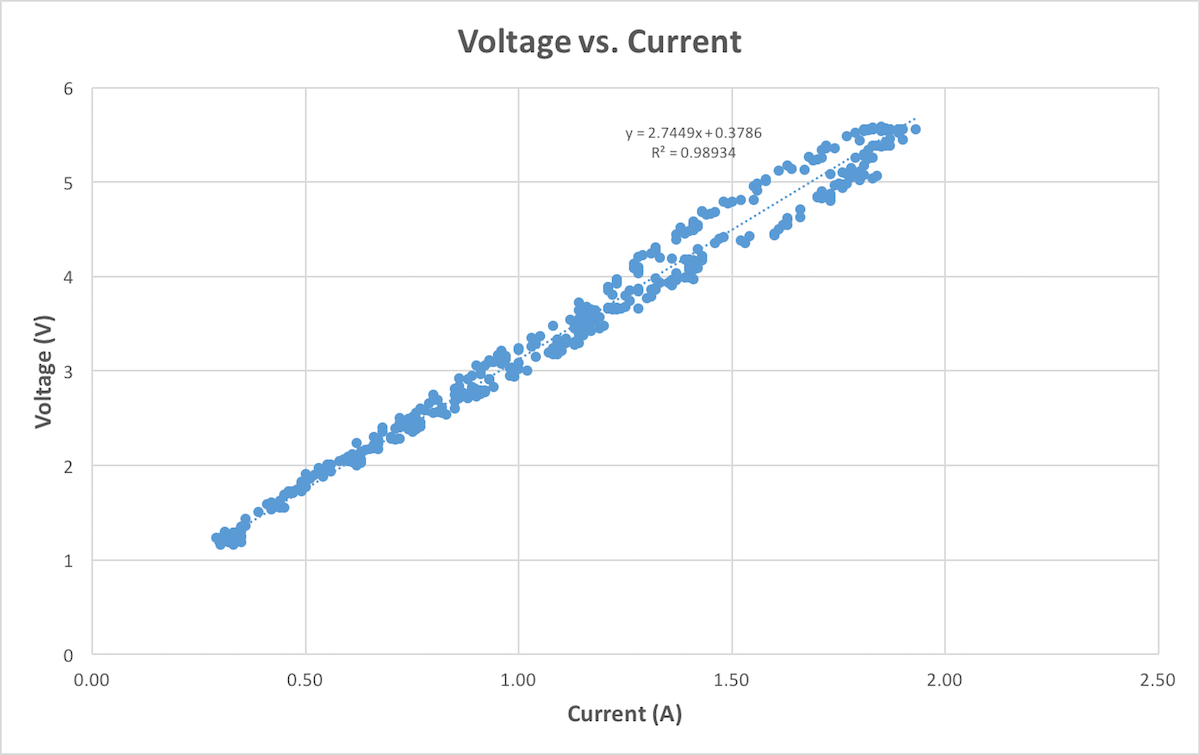


As you can see, the results are actually quite interesting. There is a clear correlation between the force created by the propeller and the voltage applied to the motor. This can be seen even more clearly when we just plot these two attributes on their own, in the third picture. The best-fit line has a very good correlation coefficient of about 0.98.
The blue dots relate to the readings taken while the voltage was increased, and the green ones relate to the readings taken when the voltage was decreased. The slight offset in the x-axis between the two plots is probably due to a delay in the response of the weighing scales (it is designed to take one reading, and not a continuously changing reading after all).
The resistance of the motor was found to be about 2.75 ohms, while the peak current draw at a voltage of 3.3V was 1.13 amps.
Power Management
Most motor controllers introduce a voltage drop, reducing the maximum voltage which can be supplied to the motors. Let’s assume that the battery can provide 3.7V and that there is an average voltage drop of 0.4V, meaning that the maximum voltage which can be supplied is about 3.3V. With fours motors running at this maximum voltage, the battery needs to be able to supply 4.52 amps of current and 14.9 watts of power. A small single cell Lithium Ion (LiPo) battery usually has around 300mAh. We can calculate an approximate flight time as follows:
The controller board will also consume some power, but it is in the order of about 20-30mA, so it won’t affect the calculations much. As the motor drivers and battery aren’t 100% efficient, I’d estimate a flight time of about 3.5 minutes. This is very similar to the flight time advertised by other miniature quadcopters which are on the market at the moment.
The LiPo I looked at had a C-rating of 25C. That means that the entire capacity of the battery can be discharged in 1/25 of an hour, allowing the maximum current draw that it can handle to be calculated as shown below. The combined current draw of the motors is well under this rating, so we are all good.
Lift
Do the motors and propellers provide enough lift in order to keep the quadcopter in the air? I put together a quick mass balance to figure this out:
| Item | Mass (grams) | Force (N) |
|---|---|---|
| Max Lift (with four motors): | 52 | 0.5101 |
| Motors & Propellors | 22 | 0.2168 |
| Battery | 10 | 0.0981 |
| Controller Circuitry | 6 | 0.0589 |
| Frame | 10 | 0.0981 |
| Overall Lift | 4 | 0.0392 |
Giving the quadcopter a reasonable upward acceleration of:
Of course the realistic acceleration will be slightly less due to losses, but this table proves that it is possible for the quadcopter to fly! It will definitely be difficult to do, but I do like a good challenge! I will probably have to redesign the frame a couple of times to make sure that the whole device is light enough that it still has enough manoeuvrability.
Next Steps
- Designing and 3D printing a light-weight frame
- Deciding on a suitable controller board
- Designing the motor controllers and power circuity
Updated: 25th May 2019 – Reformatted post